for RAZORS | SCALPELS | OTHER FINE BLADES
- Quickly and accurately produces sharpness and edge retention data.
- Uses standardised test procedures or users specific requirements.
- Automatic operation allowing operator to multitask.
- Can be used for quality control, research and development and competitor product evaluation.
- Designed to evaluate hi-tech sharpness retentive edge coatings.
- Provides valuable information on PTFE retention on razors.
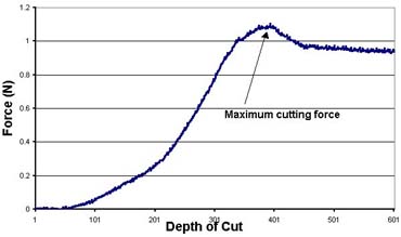
The test utilises the constant cut depth method in which the blade is pushed normally without longitudinal travel into the test media. The cutting force is recorded as a measure of the sharpness, which means the lower the force the sharper the blade. The test media is 8 mm square silicon rubber, which is bent around a 20 mm former and the cut is made into the outer periphery of this bend. This causes the rubber to open up the cut as the blade penetrates, thereby reducing the point of contact of rubber and blade to the tip of the edge only.
As the blade contacts the rubber the force increases to a maximum at which cutting starts to take place after which this cutting force falls to lower level. It is this maximum force that is used as the sharpness related figure.
In order to induce wear to the blade tip, a series of subsequent cuts are made in which the blade is oscillated over a short stroke with no cutting force readings being made. The sharpness is then re measured. This whole procedure is repeated in order to develop the wear curve for that particular blade. We have developed a specific test protocol for razors and scalpels, but the system is capable of being programmed to the users own test requirements.
This test system has been proved by extensive trials to be able to accurately evaluate blade sharpening techniques and edge coatings, providing an essential tool in blade quality control and edge coating research and development.
The rubber test media has been developed to provide an accurate and repeatable sharpness and wear performance, whilst only creating blade wear similar to that found on blades after normal use.
Machine description
The equipment is free standing in its own aluminium frame and is generally as shown in the schematic diagram. The powered test media feed unit and blade slide are mounted on top of the frame with the controlling PC, motor drive system and test media coiling/uncoiling unit underneath. The PC keyboard and monitor are mounted also on top of the frame.
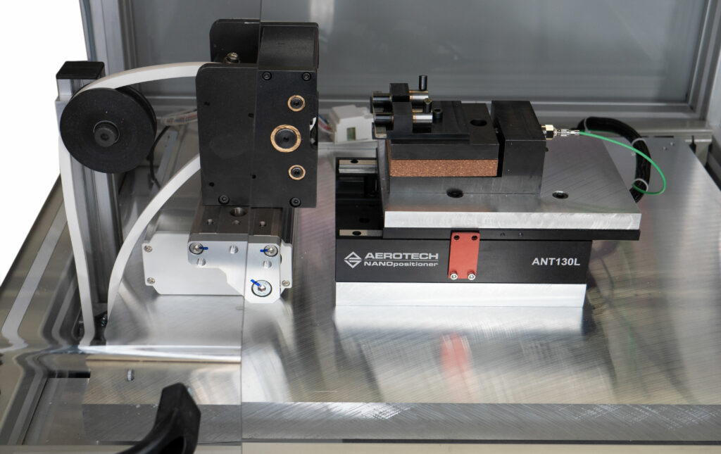 The cutting test mechanism consists of a test media feed unit, which pulls the 8mm square section rubber from a coil drum. The rubber media is driven around a radius former to ensure a controlled bend for the cutting zone. This feed motion is controlled by a programmable stepper motor drive system, giving adjustable incremental rubber feeds.
The whole of the rubber feed mechanism will be mounted on a horizontally positioned linear slide, which is oscillated by a lead screw mechanism driven by a programmable stepper motor giving adjustable stroke and speed. At the side of the unused coil of test media an automatic recoiling unit, which controls the used media. (The test media may be turned over and reused on the opposite face)
The blade-mounting unit consists of replaceable locking blade clamps, which can allow the blades to be tensioned to a pre-determined level. These replaceable clamps can be changed for optional clamps to accommodate various blade cross sections or scalpel blade shapes, thereby giving accurate and repeatable blade positioning. bar.
The blade unit is mounted to a linear low friction bearing slide, which is coupled, to a high accuracy and resolution force measuring cell. The linear slide has have a stroke length of 50 mm and is be driven by a programmable servo drive system, which is capable of operator programmed sequences, speeds and distances via the PC.
Cutting force measurement is conditioned and monitored by a proprietary signal conditioning unit feeding the force data to a PC. This PC processes the force signal, identifies peak loads and collates all readings to create a peak force curve. The software allows multiple graphs to be superimposed. The data manipulation is carried out under visual basic control and the data recorded in an Access compliant database. The system enables the operator to record all relevant blade/parameter information and print out a detailed test report for each blade test. In addition the software links to Microsoft Access database software providing storage and recall of all test data and to Excel foe in depth data analysis.
The software and control system is designed in such a way that the unit can be utilised as an edge sharpness and life development machine and not just a sharpness/life quality measurement system.
Specifications
| Size | 1800mm long x 800mm wide x 1700mm high |
| Weight | 280kg |
| Typical Test Time | Sharpness: 2 mins
Sharpness & Life: 20 mins |
| Computer Control System | PC, Windows 11 |
| Frame | Free standing aluminium with integral interlocked safety screen |
| Finish | All non-functional surfaces anodised aluminium functional steel surfaces black oxide coated |